Introduction to Unreal Engine 4
September 16, 2016 • UnrealEngine4 • 14 minutes to read • Edit
The project files can be downloaded from https://github.com/akshaybabloo/UnrealEngine_4_Notes
UnrealEngine 4 using Blueprint visual scripting system.
Note 1: This project is developed on Mac OSX 10.11.2 using UnrealEngine 4.10.2. It should work on Windows as well.
Note 2: Notes shown below may contain few lines from the original UnrealEngine Documentation.
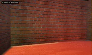
Outcome
Note 3: This is only a gif file compressed to load easily. The quality of the environment is 1000000% better than this.
Demo
Table of Constant
- 1 Requirements
- 1.3 Bump Maps (or Normal Maps) generator
- 2 Creating project
- 3 UnrealEngine overview
- 4 Blueprint editor
- 5 Let’s get started
- 6 Material
- 7 Lighting
- 8 Adding animations and interactions
- 9 Landscaping
- 10 Polishing environment
- 11 Publishing
1 Requirements
1.1 Software:
- UnrealEngine 4.7+ -> Gaming engine.
- Maya or 3DS Max -> For 3D modeling.
- Photoshop or Illustrator -> For texture.
Windows
- Visual Studio 2013 Pro or community (as per the UnrealEngine documentation, this is installed automatically)
Mac
- Xcode 5.0 or above
1.2 Hardware
According to UnrealEngine documentation.
Windows
- Windows 7 or above
- A good graphic card that supports DirectX 11.
- Quad-core Intel or AMD, 2.5 GHz or faster processor
- 8 GB RAM or above
Mac
- Mac OSX 10.9.2 or above
- A good graphic card.
- Quad-core Intel, 2.5 GHz or faster
- 8 GB RAM or above
1.3 Bump Maps (or Normal Maps) generator
Windows
- Awesome Bump -> Free
- CrazyBump -> Free
- SSBump Generator -> Commercial
- Shadermap -> Commercial
- Filterforge -> Commercial
- B2M -> Commercial
Mac
- Awesome Bump -> Free although you would have to build the files. Follow the instructions on their GitHub.
- CrazyBump -> Free
- Filterforge -> Commercial
- B2M -> Commercial
Online
- NormalMap Online -> Free
2 Creating project
Open Epic launcher and launch UnrealEngine. Goto New Project, under Blueprint (It is a node based approach where you don’t have to write an code) tab click on First Person. Make sure there are no Starter contents (i.e. rocks, land etc…). Change the location of your project and file name to suit your needs. Once all the primary configurations are done, click on Create Project.
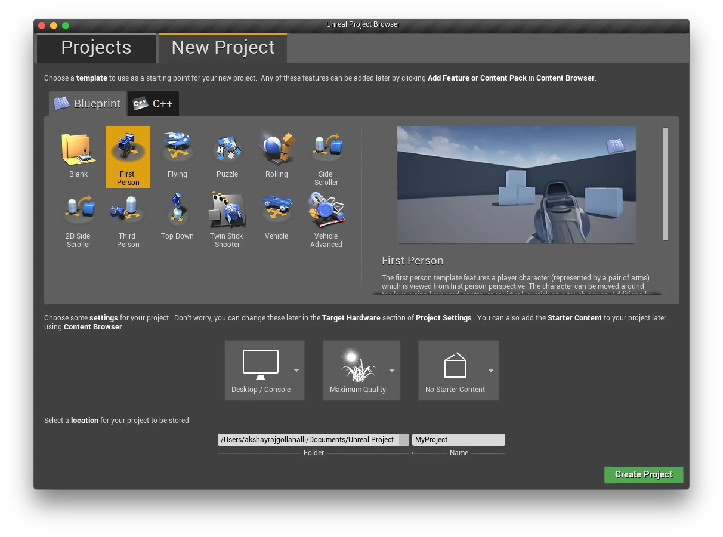
New Project
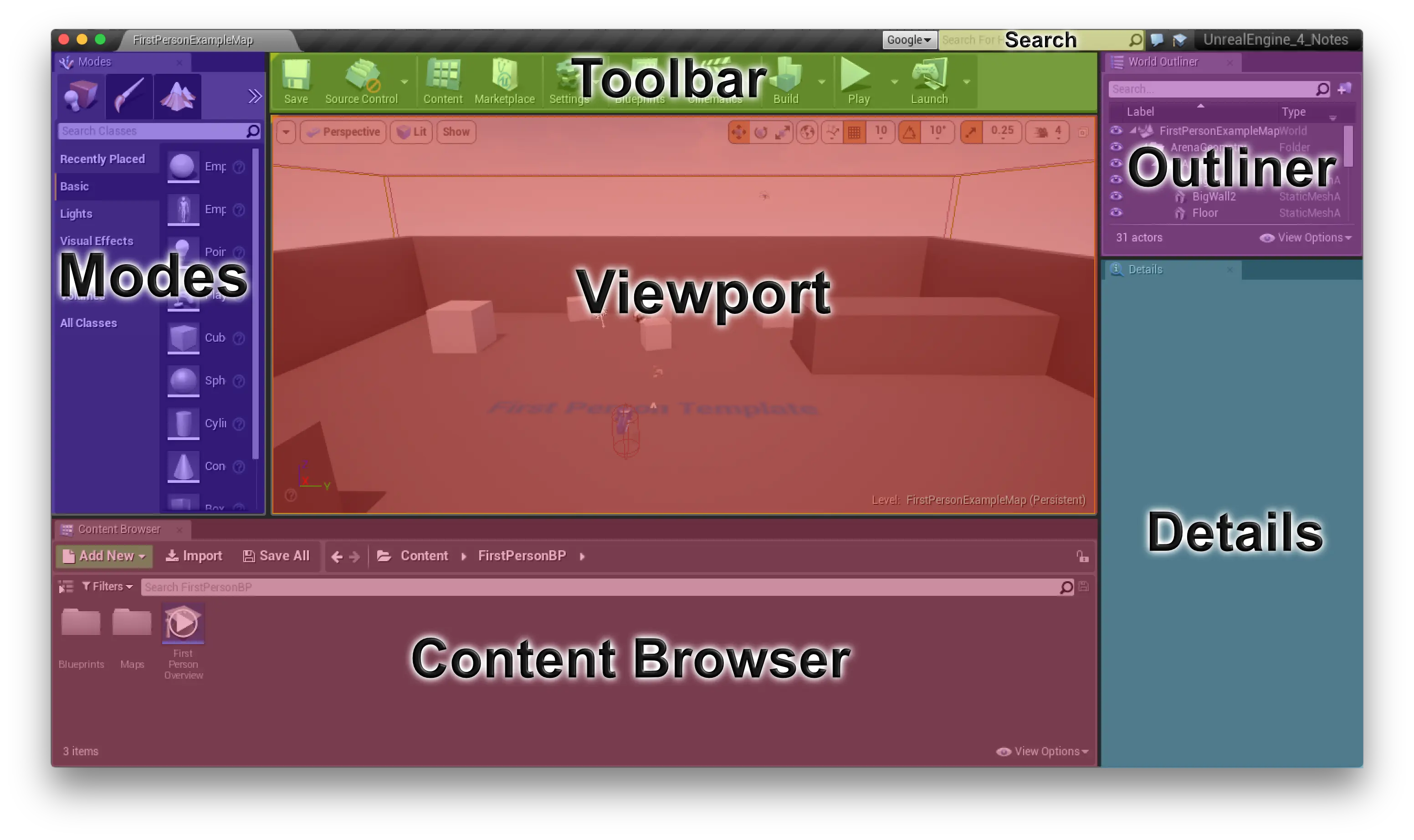
3 UnrealEngine overview
Unreal Engine Note
Tip 1: press
cmd + alt(Mac) and move the cursor on an icon to get quick help.
UnrealEngine (for me or maybe for everyone) is divided into seven parts:
- Modes - This is where all the tool to build an environment is kept.
- Content browser - All your project files can be browsed from this place.
- Details - When you click an object (Actor, Pawns, Lights, etc..) all its details are displayed here.
- World outliner (Outliner) - Whatever is available in the viewport, can be seen here. It is like a Content browser but for you viewport.
- Toolbar - Buttons to Save, Play, etc.. are here.
- Search - This is where you can search for help regarding an object.
- Viewport - Your design area or the Editor.
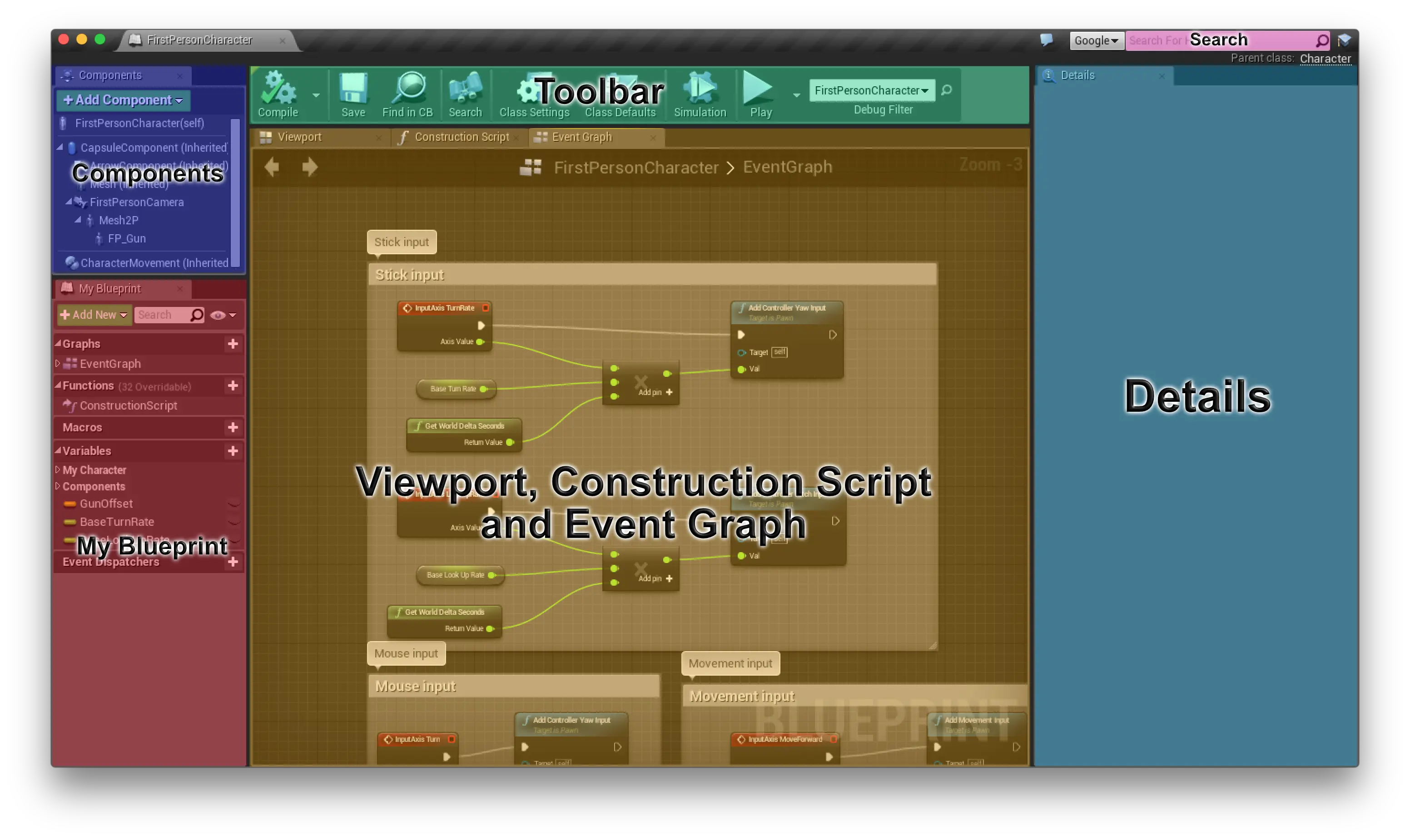
4 Blueprint editor
Unreal Engine Editor
A Blueprint is a node based visual scripting system in which you would not need to code any action or effect an actor performs.
Blueprint is divided into six parts:
- Components - Components of an actor.
- My Blueprint - An outline of Blueprint function, scripts, etc..
- Contents
- Viewport - 3D view related to a particular actor.
- Construction Script - This contains Blueprint classes.
- Event Graph - This tab contains nodes. They perform events and functions while a game is played.
- Details - Settings related to nodes.
- Toolbar - Buttons to Save, Play, etc.. are here.
- Search - This is where you can search for help regarding an object.
5 Let’s get started
5.1 Editing the environment
From the World Outliner let’s remove Cubes, Arena and Templatelabel. We don’t need them.
Next, the FirstPersonCharacter (under World Outliner) default action is to shoot balls. We would have to change it. To do that, beside the FirstPersonCharacter there is a blue link which says edit FirstPersonCharacter, this is the link to Blueprint Editor. Clicking on it will open a new window.
5.2 Blueprint editing
In Event Graph tab, look for Pawn projectile and delete it and also delete the nodes in it. We wouldn’t wouldn’t need it. Once you have removed the nodes, click on Compile button on the Toolbar, this will check for any errors. If no errors are found, a green tick would appear. Close this window.
5.3 Deleting unwanted meshes
Under Content browser Click on
FirstPerson and on the right window, double click on Meshes, this should open meshes associated with our project, in that delete First Person Projectile and First Person Projectile. You will get a window warning you that the meshes are still referenced. Click on Force Delete. Then delete the arms and gun in the same way.
5.4 Creating Maya models
A Maya 2016 model is developed and is available in UnrealEngine_4_Maya folder and fbx file is located in Import folder.
5.5 Importing fbx file
There are two ways to import an fbx file into the project that fits the scale of the project. In this case, I am using maya.
You can scale up the models while importing
fbxfiles into UnrealEngine. When you import anfbxfile you will get an option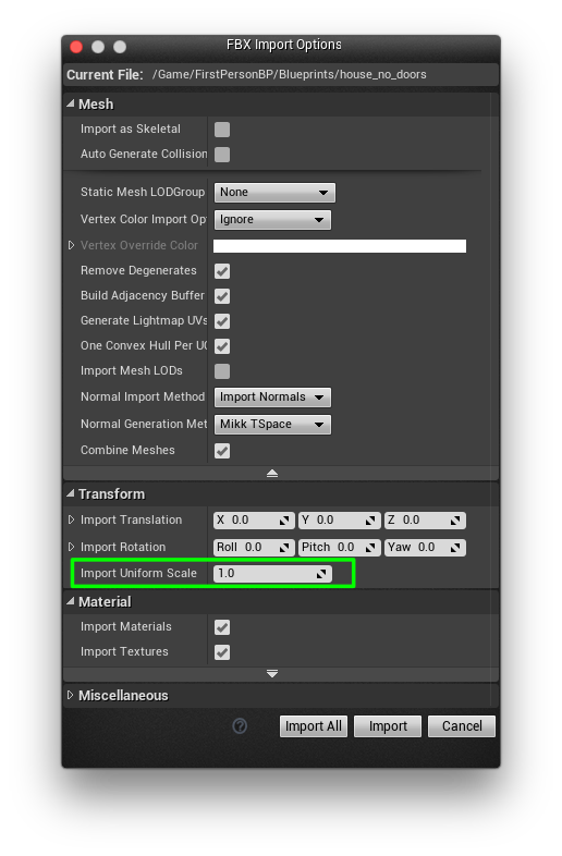
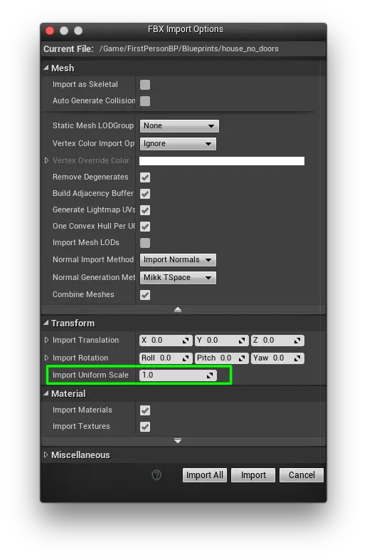
Import FBX
Whenever I import the models I usually scale it up to
100.The other way is to change the Maya environment so that the models can be imported as it is. You can check out this tutorial here.
It is recommended that you always create multiple fbx files so that the UnrealEngine doesn’t crash (if the project is big). In this case, it’s not a significant import, so I didn’t do that.
In Content Browser click on Import, browse to Import/house.fbx and click Open. You will get a pop-up FBX Import Options in that un-tick Auto Generate Collision (It creates a collision box or sphere etc.. for every object, we can do that manually). Then click on Import All.
Once you have imported your fbx file, the following files are generated:
- Meshes
- Texture (if it is associated with the model)
- Normal maps (if it is associated with the model)
- Bump maps (if it is associated with the model)
What I have done is that I have separated these files into their corresponding folders. For example, I have moved all my meshes to Content/FirstPerson/Meshes/.
5.6 Adding collusions
When you double click on the house_no_doors mesh, this will open the following editor
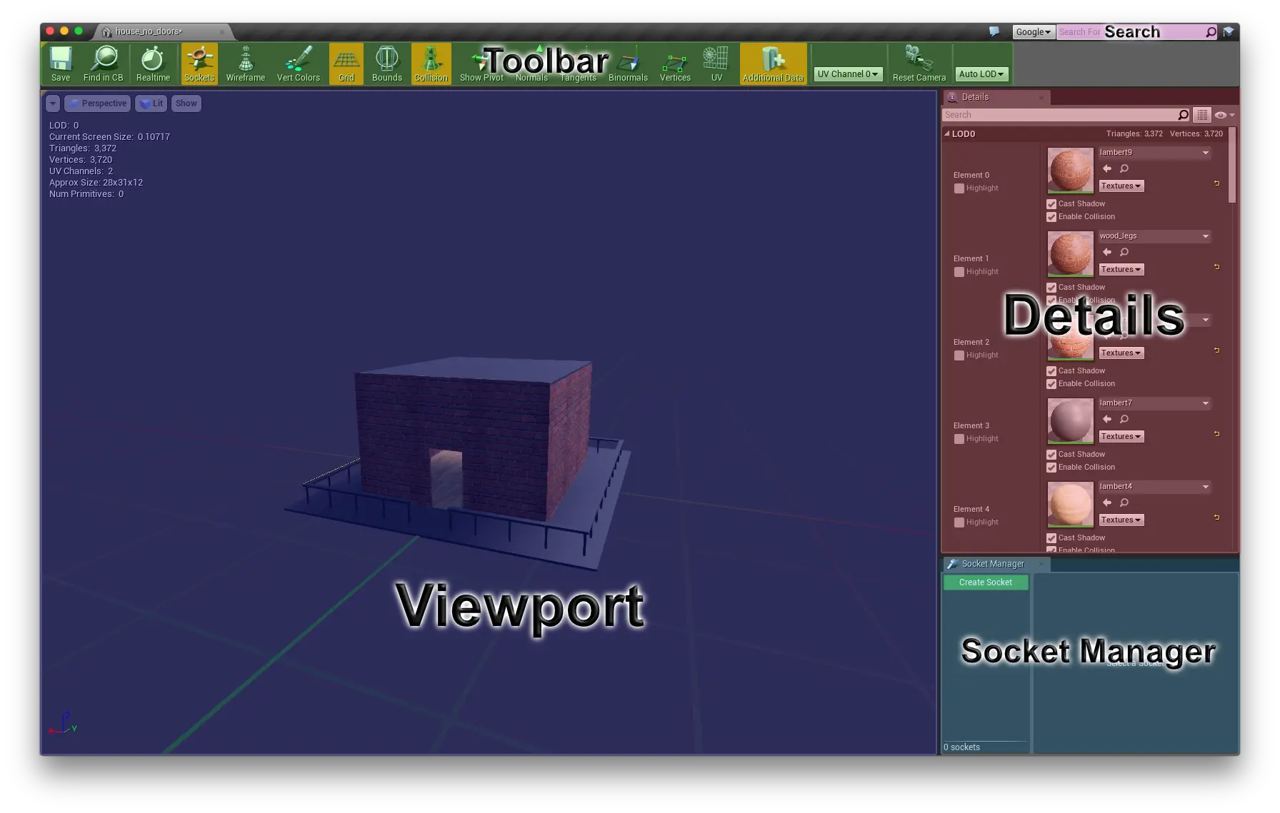
Static Mesh Editor
This editor is divided into five parts:
- Viewport - 3D view related to a particular actor.
- Socket Manager - For skeletons.
- Details - Settings related to an actor.
- Toolbar - Buttons to Save, Wireframe, etc.. are here.
- Search - his is where you can search for help regarding an object.
There are different types of colliders. Namely
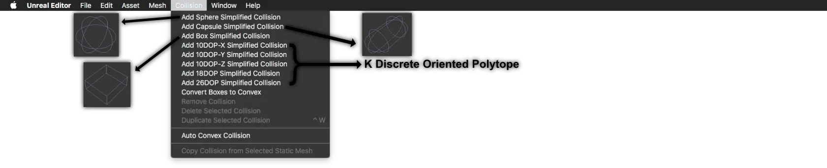
Collusion Menu
In this DOP means Discrete Oriented Polytope, which means that it will create box collision with bevels which is closest to the object or the actor. See here to understand more about it.
We will be using Blueprint for the doors but for the rest of the building, we will use mesh collider. In the Details tab (left to the editor). Scroll down and search for Static Mesh Settings in that tab change the Collusion Complexity Default to Use Complex Collusion As Simple. Save and close the editor.
Note 4: Adding Mesh collisions will be expensive. That means the rendering time would take more time, and the system will use more frames per second depending on the number of mesh collisions. But for this example, I have just created mesh collision to make it simple.
5.7 Creating Blueprints
All my Blueprints are place in FIrstPersonBP/Blueprints/. To create a blueprint right click on the Content Browser and click on Blueprint Classes, this will pop-up a window which will ask you to select a parent class that should look something like this
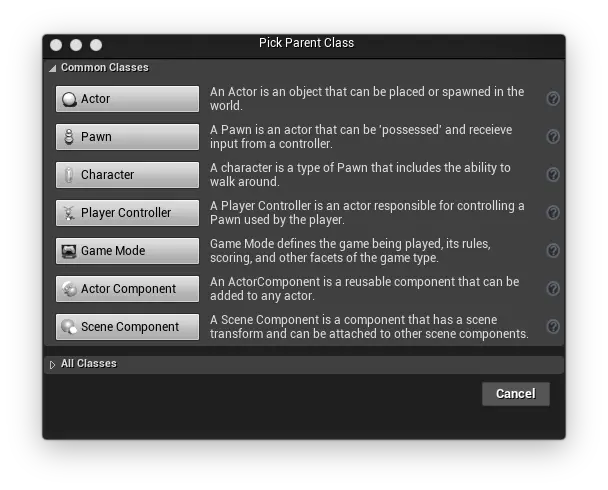
Pick Parent Class
We will create a simple Actor for this blueprint and name it as DoubleDoor. Double-click on it to open Blueprint editor. Now drag the door_left and door right into the blueprint editor. Then click on compile and save from the Toolbar.
5.8 Add models to the Viewport
Goto meshes folder and drag all the meshes and drop it in the viewport. If the models looks out of placement, you can 0 the transformation in from the details tab.
Now from the Blueprints folder drag and drop DoubleDoor blueprint into the viewport, once this is done, place this in the exact place where the door should be. Save the scene.
6 Material
6.1 Editing materials
When you move the meshes to the viewport in UnrealEngine editor, sometimes depending on the software used to export fbx files, the material is added to the meshes automatically and sometimes not. The materials may include Normals, Bump maps, occlusions, etc.. To manually add these to an existing material you would have to do the following:
On the left side of the editor under Details (make sure you have selected the model from the Viewport), search for Materials, in that tab you can see different elements associated to the static mesh. Double click on a material this will open Material Editor.
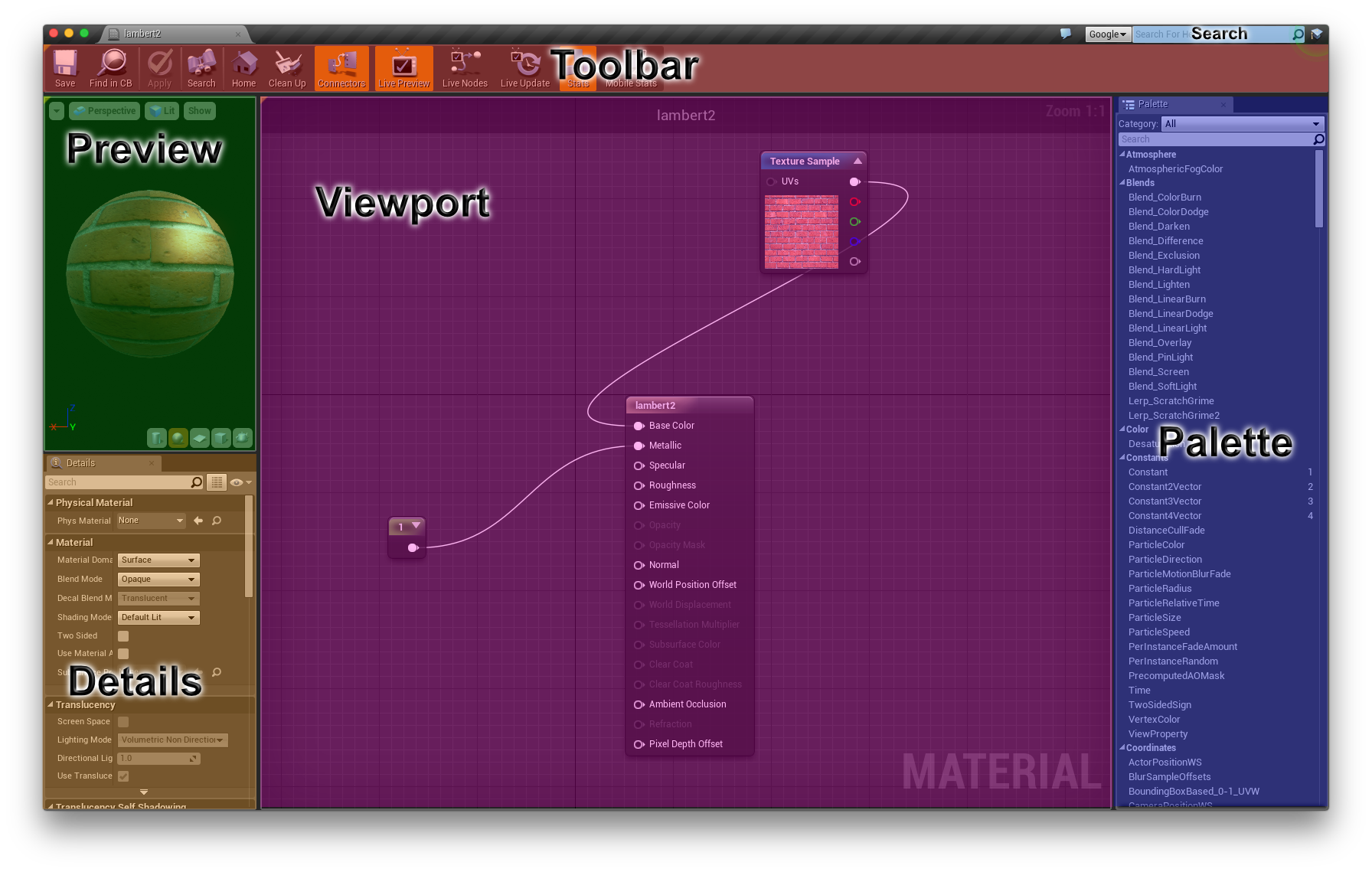
Material Editor
It consists the following components:
- Preview - Preview of the changes made to the material.
- Viewport - Node editor.
- Palette - Node menu.
- Details - Details of a selected node.
- Toolbar - Consists of save, apply, etc..
- Search - Search for components related to UnrealEngine.
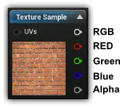
In the viewport, there are three nodes
Constant(Custom metallic effect),lambert2(actual texture from Maya) andTexture Sample(Texture added to lambert2).The
Texture Samplenode consists of RBG channels as shown in the image below
Texture Node
Once you have done the necessary changes, then you should click on
Applyand thenSave.

6.2 Shine to lambert7 texture
Let try to give a shine to one of the materials which are used in as texture to the outside railings. Do the following:
- Go to texture folder and double click on
lambert7texture, this should open material editor. - Delete
Nonenode. - let’s create a
Constant3Vector, you can right click and search for it, or you can drag or double-click the node fromPalettetab or press and hold3and left click on the mouse. - Connect this node to
Base Color. - Double click on the color to pop out color palette. Change the color as you like. Click on
Saveonce done. - Create a
Constantand connect it toSpecular. Change the value to0.6. - Create a constant and connect it to
Roughness. Change the value to0.2. - Save and close.
6.3 Creating glass
- Double click on
Glassmaterial. - Delete
Nonenode. - if a node is selected, un select it by click outside. In the
Detailstab, underMaterialchangeBlend Mode->Translucent. UnderTranslucencytab uncheckSeparate Translucencyand change theLighting Mode->Surface TranslucencyVolume. - Next, add
Constant3Vectorand make a dark green color. Add two constants0.2for Metallic and2for Specular. Then addLerp(Linear Interpolation) by pressingLand clicking left mouse button and connect it to Opacity. Next add aFresnel_Functionconnect theResulttoAlphaofLerpnode. Two constants with value0connected toAand1connected toBofLerpnode. - Now copy two
Constants,LerpandFresnel_Functionand paste it. Connect the result to Refraction. - Create another constant of
0and connect it to Roughness.
The nodes should look something like this:
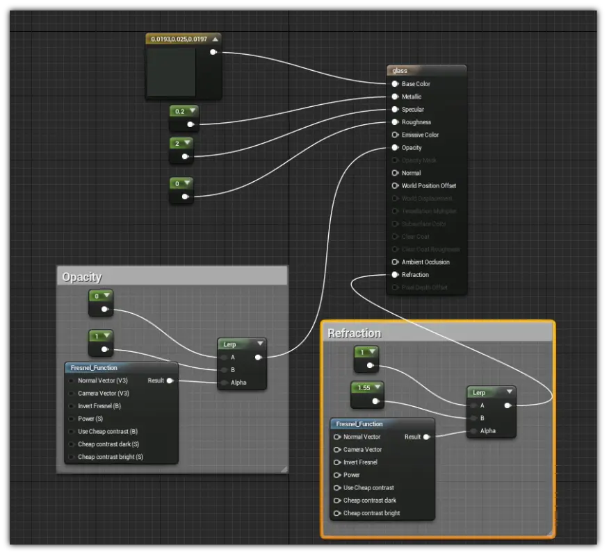
Glass Node
6.4 Adding reflections
In the Modes tab search for Sphere Reflection Capture and drag it near the glass door. In the Details tab search for Reflection Capture and change the value of Influence Radius this will change the outer radius of the sphere.
If any changes are made, do not forget to click on Update Captures.
7 Lighting
7.1 Adding lights
In Modes tab, click on Lights, I will add a Spot Light on top of my table by dragging it into the Viewport. You can change the Perspective to Top to make it easy to move the spotlight.
Once you have placed your lights click on the small arrow beside Build button in the Toolbar and click on Build Lights Only. At this point if you have a multiple number of light on a surface you will get a small red mark on the lights, and you might get an error while building the lights.
7.2 IES Profiling
An IES profiles give you the shape and size of the light rays that come from a spotlight. IES files are usually given out by the lights manufacturers, let’s consider GE Lighting if you scroll down in that website you can find IES/LDT files.
You can use this file by importing it into UnrealEngine and drag & drop on the IES Texture under Light Profiles by selecting a spotlight.
An example of these can be seen here.
8 Adding animations and interactions
8.1 Adding sockets
Double click on door_hinge. Add a box collider to it. To add sockets to the hinge do the following
from the menu bar click on Window -> Socket Manager. On the left side of the screen below you will see a tab called Sock Manager in that click on Create Socket and name the socket as SocketDoorL and place it as shown in the image below. Likewise, create another socket and place it as shown.
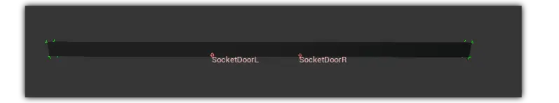
Sockets Hing
Save and close the window.
Create a blueprint class and name it as DoubleDoorHinge to this add door_hinge, door_left and door_right.
Drag the door_hinge onto the DefaultComponent to make it as a parent. In the Details tab, search for Sockets. In that beside the text box click on the magnifying glass to browse available sockets. Make sure you assign the correct socket to the right door.
8.2 Adding triggers
Open DoubleDoorHinge if not already open. Add a sphere collider and increase its radius so that both the doors are covered. Go to Event Graph, in that there is a node called Event ActorBeginOverlap click and drag a connect to outside of the node and search for Add Timeline..., this will create a new node. Next under My Blueprint Variables -> Components click on the trigger, this will open its details in Detail pane. In that pane infer Events click on the + beside On Component End Overlap this will create a node.
Click on the trigger under components to bring its details. In that details pane search for Collusion change collusion preset to Custom. Ignore all except Pawn
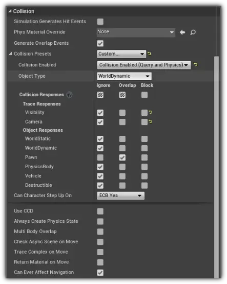
Collusion Door
Next right click on the grid and search for Lerp under Float tab. Right click on A and B and choose Promote to Variable. Rename it in the Details pane as Closed and Opened.
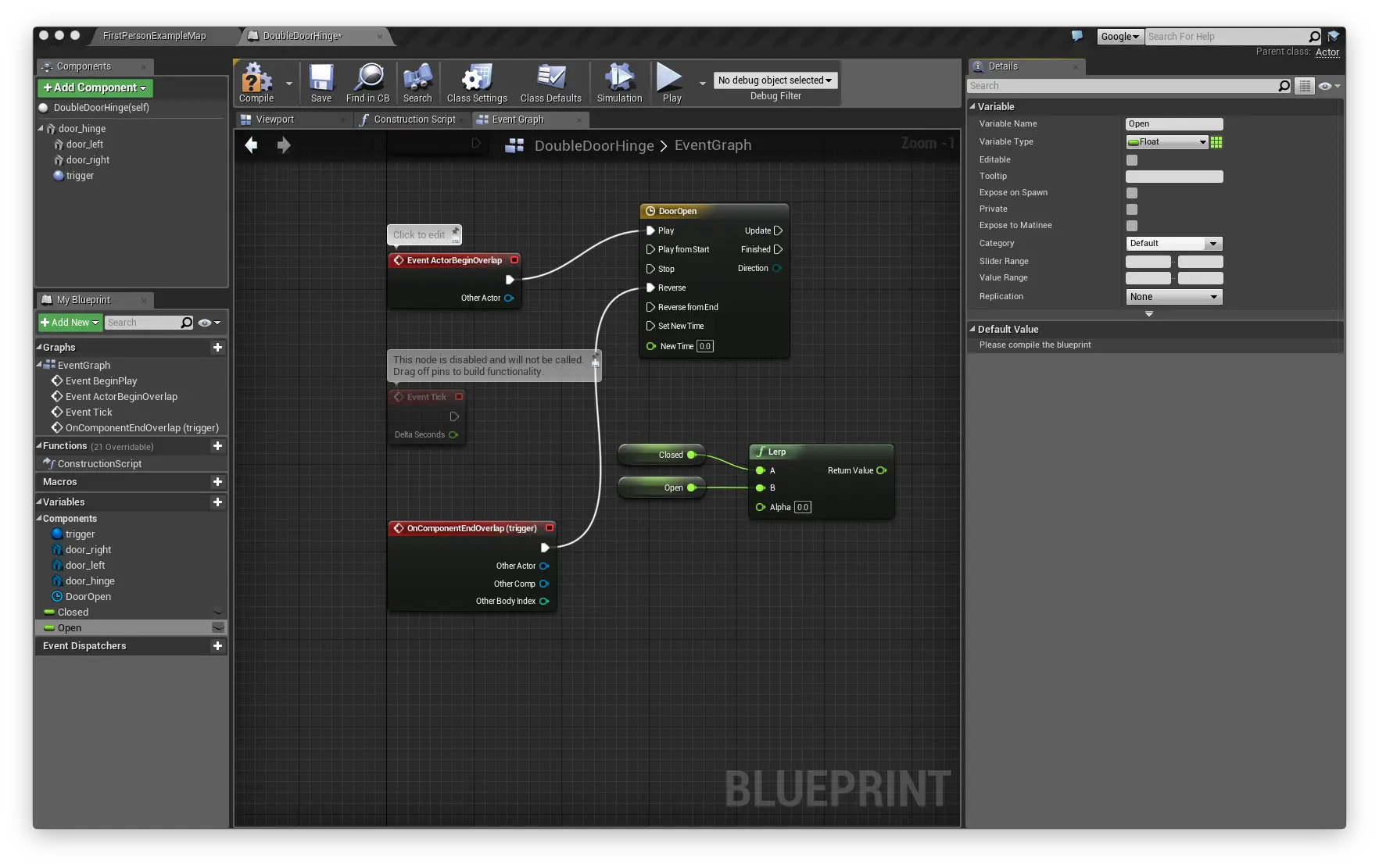
Door 1
8.3 Adding animations
Double click on DoorOpen node to open the timeline, this would be empty. Click on f+ to add float timeline, name it as DoorOpenAnimation. Right click and add a key at Time 0.0 and Value 0.0. Add another key at Time 1.5 and Value 1.0. Select both keys, right-click on it and select Auto this will generate a curve. Go back to the event graph and connect DoorOpenAnimation to Lerp’s Alpha.
Now lets add a translation to both the doors. Click on door_left and RMB and search for SetRelativeLocation(door_right) and SetRelativeLocation(door_left). In SetRelativeLocation nodes right click on New Location and click on Split Struct Pin, this will split into x, y & z connect all the nodes as shown in the image below:
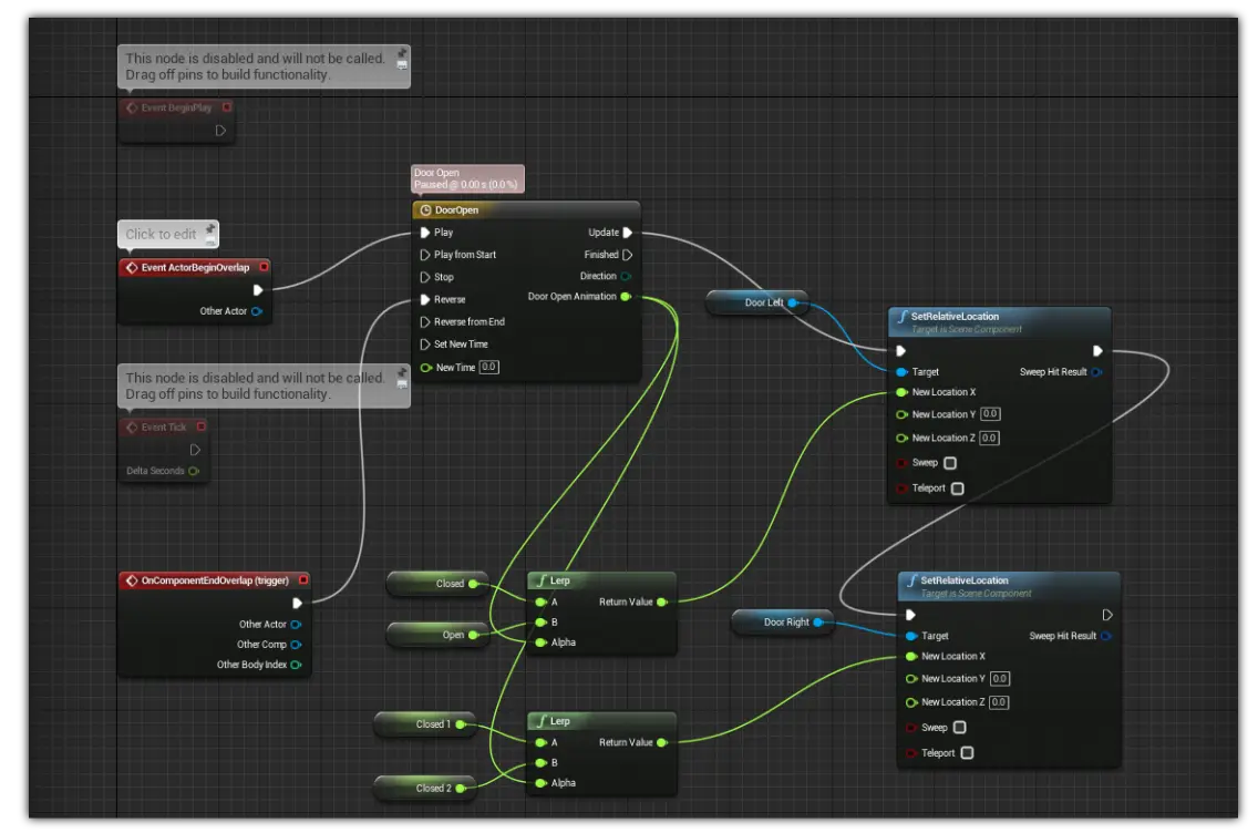
Door Animation
Don’t forget to compile and save once done.
9 Landscaping
9.1 Creating grass material
Create a diffuse and normal from one of the software given in the requirements and import it into the Texture folder. UnrealEngine will convert it into texture automatically. Now, go to the materials folder, right click and Material, this will open a Node editor.
In that press T + LMB to create a texture node, under Details pane, browse to grass_COLOR then select it. Do the same thing again but this time browse to grass_normal, attach the node to grass node as shown below:
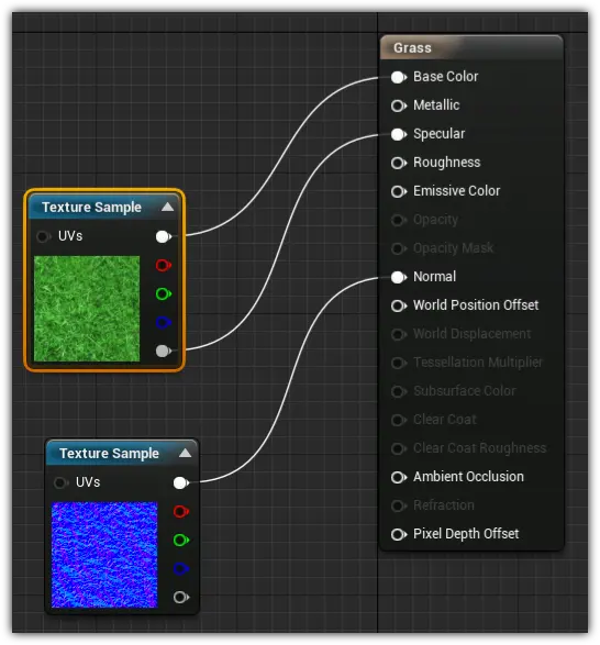
Make Texture
9.2 Adding terrains
To add terrains, click on the Landscape icon in Modes, this will populate a green mesh in the viewport. Move the mesh below the building. Under modes New Landscape, browse to the Grass material. Reduce the Section Size to 31x31 and click on create.
Once create just start painting on it. See other tools for more fine detailing the landscapes.
9.3 Foliage
Foliage can be found in the Modes. You can drag and drop any meshes like tree or grass into this and start putting on the ground.
10 Polishing environment
10.1 Global Post Processing
From the World Outliner search for PostProcessVolume, this should be under Lighting folder. In that search for Post Process Volume and click on >Settings tab, this is where you can change the global visual settings.
Open the project and look it to the various setting I have changed to make the visualization look real.
11 Publishing
The final step is to publish the environment.
To do that click on File -> Package Project -> Select your platform.
Note 5: If you are in Windows you can only package the game for Windows only but not for Mac and Linux. It goes the same for Mac and Linux.
